With a frequency synthesizer, you can produce output frequencies of various multiples of a single reference frequency. Its main application is to generate local oscillator (LO) signals for up-conversion and down-conversion of RF signals.
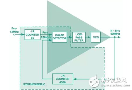
The frequency synthesizer operates in a phase-locked loop (PLL), where the phase-frequency detector (PFD) compares the feedback frequency with a certain frequency division of the reference frequency (see the figure below). The output current pulse of the PFD is filtered and integrated to generate a voltage. This voltage drives an external voltage controlled oscillator (VCO) to increase or decrease the output frequency, driving the PFD's average output to near zero.

Phase Locked Loop (PLL) Block Diagram
So what key performance parameters need to be considered when selecting a PLL frequency synthesizer?
1, phase noiseFor a carrier frequency of a given power level, the phase noise of the frequency synthesizer is the ratio of the carrier power to the power at a specified frequency offset (typically 1 kHz for the frequency synthesizer) at a bandwidth of 1 Hz. The in-band (or near-carrier) phase noise mainly depends on the frequency synthesizer, in dBc/Hz; the VCO noise contribution is filtered out in the closed loop by high-pass filtering.
2, reference spuriousIt is the frequency component that appears at the discrete offset frequency generated by the internal counter and the charge pump operating at the PFD frequency. Mismatches in the high and low currents generated by the charge pump, charge pump leakage, and insufficient power supply mishap increase this spur. The spurious noise mixes above the desired signal, reducing the receiver's sensitivity.
3, lock timeThe lock time of a PLL is the time it takes to jump from one specified frequency to another specified frequency within a given frequency tolerance. The size of the jump is typically determined by the maximum jump that must be completed by the PLL when operating in the allocated frequency band. The GSM-900 has a step size of 45 MHz and the GSM-1800 has a step size of 95 MHz. The required frequency tolerances are 90 Hz and 180 Hz, respectively. The PLL must complete the required frequency steps in less than 1.5 time slots, each 577 μs.
Under Desk Foot Warmer,Under Table Foot Warmer,Electric Foot Warmer Under Desk,Under Desk Electric Foot Warmer,Foot Warmer Under Office Desk
Ningbo Sinco Industrial & Trading Co., Ltd. , https://www.newsinco.com