The microstrip antenna, as a new type of antenna successfully researched in the 1970s, has the advantages of simple structure, light weight, low profile, easy conformal installation with the aircraft surface and integration with microstrip circuits, etc. in mobile communication, aviation. Space, electronic countermeasures and radar have been widely used. However, the microstrip antenna also limits its application range due to its low gain and narrow bandwidth (usually only bandwidth (0.7%-7%). With the development of frequency hopping and spread spectrum communication technology in military communication and mobile communication, It is more and more urgent to require the antenna to be broadband at the instantaneous frequency. In particular, China is currently in the transitional phase of 2G-3G, and the rapid growth of mobile communication users has caused the communication system to be continuously updated and expanded. To reduce interference in wireless communication. Reducing the cost requires the antenna to operate in a wide frequency band. Therefore, the research on the broadband technology of the microstrip antenna has become an urgent research topic.
At present, the broadband technology of microstrip antennas mainly includes: increasing the thickness of the dielectric substrate, reducing the dielectric constant of the dielectric; modifying the equivalent circuit, such as additional parasitic patches, using electromagnetic coupling feeding, etc.; additional impedance matching network; changing radiation The shape of the plate, such as the fractal structure or the curved edge structure, etc., Chang, Long and Richards et al. obtained a 20% antenna operating band width by experimentally increasing the thickness of the substrate. Purchine, Aberie and Birtcher et al. regard the microstrip antenna as a resonant circuit. A varactor diode is connected between the radiant panel of the microstrip antenna and the grounding plate, and the microprocessor is used to control the change to the varactor. With reverse bias, the application tuning method can operate continuously over a bandwidth of 1.55 GHz to 1.93 GHz (corresponding to 22%). An.Nanwelaers and Capelle add a reactive matching network between the input of the microstrip antenna and the microstrip line feeder to obtain an antenna operating band of 16.82%. Fang Yang and Xue Xia Zhang et al. used an E-shaped patch antenna to achieve a bandwidth of 30.3% in the wireless communication frequency range.
It can be seen that the bandwidth of the widened microstrip antenna has been greatly improved, but the above methods are also insufficient. If a microstrip antenna with a thick substrate causes a significant increase in surface wave effect, the volume and weight of the antenna will increase. The use of an impedance matching network or a method of modifying the equivalent circuit will result in theoretical analysis. Complexity and difficulties in antenna fabrication; in addition, the method of changing the shape of the radiant panel places higher demands on antenna manufacturing tolerances. Based on the above analysis, the method of introducing the air layer effectively broadens the working frequency band of the antenna. The antenna has good radiation characteristics in the whole working frequency band, and the antenna has a simple structure and is easy to manufacture.
2 Design principlesThe dual-frequency microstrip antenna designed in this paper works in the frequency range of S-band (2.0GHz-4.0GHz), and its design specifications are:
(1) Work center frequency 3.0GHz:
(2) Standing wave ratio VSWR ≤ 2.0;
(3) Antenna relative bandwidth BW ≥ 10% In the design of a common rectangular microstrip antenna, the material and thickness of the dielectric plate can be determined according to the required bandwidth and gain. Generally, the size of the radiation sheet can be obtained from the following two equations according to the center frequency at which the antenna operates:
 , (1)
, (1)
 , (2)
, (2)

(3)
Where W and L are the width and length of the radiating element, respectively. 
 For the line elongation,
  Is the dielectric equivalent dielectric constant.
Since the two-layer microstrip antenna with air layer is used in this paper, the equivalent dielectric constant formula of the dielectric layer can be calculated by cavity mode theory as follows:
 , (4)
, (4)
Where is the thickness of the air layer,  For the thickness of the dielectric layer,
  Is the dielectric constant of the medium.
when  The empirical formula for the bandwidth of the microstrip antenna can be expressed as:
 , (5)
, (5)
among them  For the center frequency,
  The thickness of the dielectric substrate.
In order to obtain broadband characteristics, a medium having a relatively small dielectric constant should be used as the substrate. The medium we use here is Rogers RT/duroid 5880 (relative dielectric constant)  Loss tangent
  ). In theory, the grounding plate can be regarded as infinite. However, in actual engineering design, the grounding plate size should be as small as possible in consideration of many factors such as antenna mounting size, weight and cost. In actual engineering applications, the local board width is satisfied
  When you can, you can think of the floor as infinite.
Combined with the above factors, the final designed antenna size is:
Radiator size:  ;
;
Ground plate size:  ;
;
Antenna thickness:  The air layer has a thickness of 2 mm and the dielectric layer has a thickness of 1 mm.
The design of the antenna is shown in Figure 1 below:
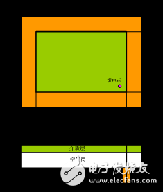
Figure 1 Antenna top view and side view
3 antenna simulation analysisThe above antenna is simulated by HFSS 10.0, and the return loss diagram, voltage standing wave ratio (VSWR) diagram of the antenna and the radiation direction pattern of the antenna are obtained as follows:
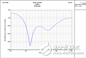
Figure 2 Antenna return loss simulation diagram
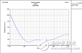
Figure 3 Antenna standing wave ratio diagram
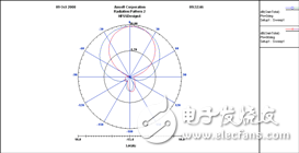
Figure 4 Antenna radiation pattern (  )
)
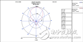
Figure 5 Antenna radiation pattern (  )
)
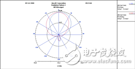
Figure 6 Antenna radiation pattern (  )
)
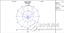
Figure 7 Antenna radiation pattern (  )
)
As can be seen from Figures 2 and 3,  When the antenna operates at 2.97GHz-3.94GHz, its relative bandwidth reaches 28.12%, which satisfies the requirements of antenna wideband operation.
From the antenna pattern (blue on the E side and red on the H side), it can be seen that when the antenna resonant frequency is 3.1 GHz, the main radiation direction of the antenna is  At this time, the gain of the antenna is 9.280dB, and the backward radiation of the antenna is small (-6.981 dB), and the front-to-back ratio is about 16.261dB.
In the antenna operating frequency band, when the frequencies are 3.0GHz, 3.7gGHz and 3.9GHz respectively, the antenna radiation pattern is basically the same as the resonant frequency, indicating that the antenna has good radiation characteristics in the entire working frequency band.
Since the size of the antenna grounding plate is limited and cannot be considered as an infinite condition, the antenna has backward radiation. In the case where the space occupied by the antenna is not strict, the backward radiation of the antenna can be reduced by appropriately increasing the size of the ground plate.
To illustrate the superiority of the designed antenna performance, we compared it to a conventional single-layer microstrip antenna. The ordinary single-layer microstrip antenna is simulated. The return loss map, the standing wave ratio map and the radiation pattern of the resonant frequency point are as follows:
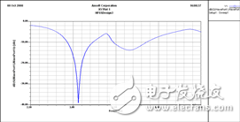
Figure 8 Simulation diagram of common antenna return loss
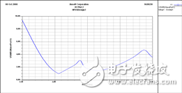
Figure 9 Simulation diagram of common antenna standing wave ratio
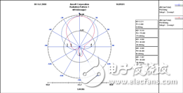
Figure 10 Ordinary antenna radiation pattern (  )
)
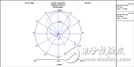
Figure 11 Antenna radiation pattern (  )
)
It can be seen from FIG. 8 and FIG. 9 that the working frequency bands of the common single-layer microstrip antennas are 2.92 to 03.24 GHz and 3.46 to 3.88 GHz, respectively, and the relative bandwidths are 10.39% and 11.44%, and the antennas are in the frequency range of 3.25 to 3.45 GHz. The impedance matching is poor. It can be seen that the double-layer microstrip antenna with air layer effectively improves the impedance matching of the antenna, and the working bandwidth of the antenna is obviously larger than that of the ordinary single-layer microstrip antenna. As can be seen from Fig. 10 and Fig. 11, the radiation characteristics of the conventional microstrip antenna are substantially the same as those of the microstrip antenna with an air layer.
From the above analysis, we can conclude that the microstrip antenna with air layer has good overall performance. The antenna has a high gain while ensuring broadband operation, and its backward radiation is very low.
4 ConclusionIn this paper, the microstrip antenna with air layer is used to realize the broadband operating characteristics of the antenna, and the antenna is compared with the common single-layer microstrip antenna. The simulation results show that the antenna has good radiation characteristics in the whole working frequency band under the premise of ensuring broadband operation. In addition, the designed antenna has a simple structure and is convenient to manufacture, which reduces the weight of the antenna to a certain extent, thereby saving the antenna cost and having a good application prospect in the antenna engineering.
Onlyrelx recharge and refill vape pod disposable vape pen is portable and fashion disposable electronic cigarette, disposable ecigs pen are trending featured vape pen for vapors as it's safety and easy to use. Disposable vape pod,disposable vape, wholesale vape,vape wholesale,vape pen manufacturer and supplier.disposable vape pen,disposable electronic cigarette,disposable ecigs pen,disposable ecigs stick,disposable e-cigs pen,disposable vape factory,disposable vape pod,disposable vape device,vape pen,vape stick, vape wholesale,wholesale vape,customized dispsoable vape pen,customized vape pen,OEM&ODM disposable ecigs pen,disposable electronic cigarette wholesale, wholesale disposable electronic cigarette,distribute vape pen,vape pen distribute,high quality vape pen,high quality vape pod,rechargeable disposable vape pen,refillable vape pen,refilling electronic cigarette,rechargeable disposable electronic cigarette,refillable vape pod,disposable refillable ecigs,disposable refilling e-cigs pen,refillable e-cigs pen
rechargeable disposable vape pen,refillable vape pen,refilling electronic cigarette,rechargeable disposable electronic cigarette,refillable vape pod
Shenzhen Onlyrelx Technology Co.,Ltd , https://www.onlyrelxtech.com