The PC and multiple single-chip microcomputers can also form a multi-level control system. Generally, the PC is the latter stage, and the minimum system of multiple MCUs is the pre-stage. The communication is generally composed of two independent modules, namely a single chip communication module and a PC communication module.
1. Design of single chip communication moduleThe serial port portion of the 51 MCU has two physically independent data buffers SBUF, but the addresses of the two buffers are one (99H). This buffer is used to send and receive data. The special registers SCON and PCON control the operation of the serial port and the baud rate setting of the communication. The timer acts as a baud rate generator. The CPU and SBUF write data to send data, and the CPU reads data from SBUF to receive data.
The serial port of the MCU 51 is a full-duplex serial communication port. The 0 serial port control register is SCON.
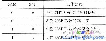
SMO and SMl: Working mode selection bits, as listed in the table.

The UART in the table is asynchronous serial communication.
SM2: Allows mode 2 and mode 3 multi-machine communication.
REN: Allows serial reception.
TB8: In mode 2 and mode 3, it is the 9th bit of the transmitted data.
RB8: the ninth bit of the received data in mode 2 and mode 3; in mode 1, if SM2 = 0, RB8 is the stop bit of the received data.
TI and RI: Send and receive interrupt flags indicating whether data has been sent or received, set by hardware, and cleared by software. Because the RS-232 interface of the PC is controlled by the 8250 chip, the general PC/XT and PC/AT machines use RS-232 to communicate with other devices using 8-bit data bits (less than 8 bits of data). Therefore, it is determined that the microcontroller must be set to mode 1.
Working mode 1: When SMO and SM1 are 0, the serial interface is selected to work mode 1, which is an 8-bit asynchronous communication mode with variable baud rate.
The transmit data is output on the TxD terminal, and each frame of information is 10 bits: one start flag bit 0, 8 data bits, and one stop bit 1. The data is sent to the buffer SBUF first when it is sent, and then the transmission is initiated. After the data is sent, the interrupt flag TI is set to 1.
At the time of reception (BEN-1), the data is input from RxD. When the first 1-to-0 transition edge is sampled, the receiver is started; after the start bit is confirmed, one frame of information is received; when RI=O, the stop bit is received. When 1 or SM2 =0, the stop bit enters RB8, the interrupt flag bit RI is set to 1, and a frame of data is received.
The baud rate is set as the baud rate generator. For this reason, Timer 1 must be in mode 2, ie automatic reload mode. TL1 acts as an 8-bit counter and TH1 acts as a constant buffer. When the TL1 count overflows, the constant in TH1 is sent to the TLO, causing TL1 to recount from the initial value again. Timer 1 produces a pulse with a fixed frequency duty cycle of 1:1, and the baud rate can be determined by the set time constant.

Where: fosc is the main oscillation frequency, 6 MHz is selected.
When the baud rate is 1 200, TH1 = TLl = OF3H.
The line used for communication is a general twisted pair power cord. The communication distance is generally within 30 m. If the communication distance is relatively long, it must be considered to be driven by photoelectric isolation or current loop, and the distance can reach 1000 m. When the baud rate is 300, the problem is not serious, the communication is reliable, and there is no special requirement for the communication line.
Zysen offer Straight Waveguide, from WR6 to WR975, length is customized according to requirement, Quick lead time 2 to 3 weeks.
H Bend Waveguide,Straight Waveguide,Waveguide Pressure Window,Microwave Straight Waveguide
Chengdu Zysen Technology Co., Ltd. , https://www.zysenmw.com