The ability of a rocket launcher to quickly launch a fire attack is an important factor in measuring the operational performance of its weapon system. Before the Rockets can accurately strike the target, they must be accurately leveled. At present, when the troops are leveling the rocket body platform, the leveling process is complex and the coordination requirements are high. The leveling process usually requires three people to cooperate with each other. One person stands on a ladder and observes the leveling instrument placed on the leveling table of the slewing ring. The two persons are manually operating two jacks under the car. Generally, after many adjustments, the body can be fully suspended. To the level. After checking and adjusting, if the body level changes, repeat the above leveling process. This leveling method takes a long time, the leveling process is cumbersome, time-consuming and laborious, and it is inconvenient for command and coordination, and the accuracy cannot be guaranteed. Therefore, the military is in urgent need of an indicator that can dynamically display the body posture and indicate the operation of the operator. Based on the STC12C5616AD microcontroller, this paper designs an operation indicator that can automatically display the tilt state of the vehicle body platform.
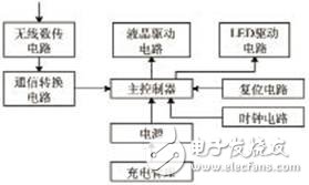
The composition and working principle of the operation indicatorThe structure of the operation indicator is shown in Fig. 1. It is composed of a main controller, a wireless data transmission module and a liquid crystal display. Its working principle: The operation indicator receives the longitudinal and lateral tilt angle data output from the tilt detector through the wireless data transmission module, processes and calculates the data, and then displays the vertical and horizontal tilt angles of the vehicle body through the liquid crystal screen. According to the calculation result of the data, the direction in which the two left and right jacks need to be further adjusted is indicated. The tilt detector is placed on the turntable level check seat. Two operation indicators are respectively attached to the two jacks or worn on the operator's arm. The two operators observe the respective indicators to level the body. The liquid crystal display adopts the 12864 liquid crystal screen of COG encapsulation, adopts the serial SPI bus line to drive, this kind of liquid crystal screen drives the chip and is integrated on the glass substrate directly, the volume is small, the electricity is saved, the circuit design of the back light is flexible.

Figure 1 Structure of operation indicator structure
Main controller selection and circuit design
Main controller selection
The operation indicator's control core selects STC12C5616AD one-chip computer. The chip has the following features:
(1) High speed: 1 clock/machine cycle, enhanced 8051 core, average command speed is 8~12 times faster than standard 8051.
(2) Wide voltage: 5.5V~3.3V.
(3) Adding a second reset function pin (high reliability reset, adjustable reset threshold voltage, this function is not required when the frequency is "12MHz").
(4) Increase the external power-failure detection circuit, can save the data into EEPROM in time when losing power, do not need EEP while working normally.
(5) Low-power design: Power-down mode (wake-up by external interrupt), support for falling/rising edge and remote wake-up.
(6) Low-power design: Idle mode (can be wake-up by any one interrupt); Power-down mode (wake-up by external interrupt), support for falling/rising edge and remote wake-up.
(7) Operating frequency: 0~35MHz, equivalent to 8051:0~420MHz.
(8) Clock: The external crystal or internal RC oscillator is optional and set when the ISP downloads the programming user program.
(9) 8/16/20/32/40/48/52/56/60/62K-byte on-chip Flash program memory with over 100,000 write/rewrition times.
(10) 1280-byte on-chip RAM data memory
(11) ISP/IAP, in-system programmable/in-application programmable, no programmer/emulator required.
(12) 8-channel, 10-bit high-speed ADC with speeds up to 250,000 times per second. 2-way PWM can also be used as 2-channel D/A.
(13) 2-channel capture/compare unit (PWM/PCA/CCP) can also be used to implement 2 timers or 2 external interrupts (support for rising/falling edge interrupts).
(14) 4 16-bit timers, compatible with the 8051 timer T0/T1, 2 PCA 2 timers.
(15) Programmable clock output function, T0 outputs clock at P3.4, T1 outputs clock at P3.5, and BRT outputs clock at P1.0.
(16) Hardware watchdog (WDT).
(17) High speed SPI serial communication port.
(18) Full-duplex asynchronous serial (UART), compatible with the 8051 serial port.
(19) Advanced instruction set structure, compatible with the common 8051 instruction set, with hardware multiply/divide instructions.
(20) General-purpose I/O ports (36/40/44), after reset: quasi-bidirectional port/weak pullup (normal 8051 legacy I/O port) can be set in four modes: quasi-bidirectional port/weak Pull, push-pull/strong pull-up, input/high resistance only, open-drain capability of each I/O port can reach 20mA, but the entire chip does not exceed 100mA.
car key cover,key holder for keychain,car key fob cover,key fob protector,honda accord accessories
Dongguan Metalwork Technology Co., LTD. , https://www.dgdiecastpro.com