Generally, six terminals are connected on the three-phase AC motor wiring frame. When the motor nameplate is marked with a Y-connection method, D6, D4 and D5 are connected, D1~D3 are connected to the power supply; when the â–³ connection method is used, D6 Connected to D1, D4 is connected to D2, D5 is connected to D3, and then D1~D3 are connected to the power supply. See the connection method connection shown in Figure 1.
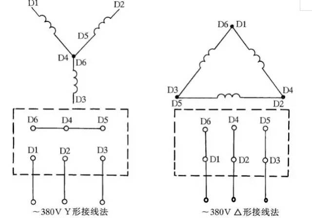
Figure 1 Three-phase AC motor Y-shaped and delta-shaped wiring method
Second, three-phase hair dryer wiringThere are some three-phase blowers with six terminals, and the wiring method is shown in Figure 2. The â–³-connected method should be connected to the 220V three-phase AC power supply, and the Y-connected method should be connected to the 380V three-phase AC power supply. Generally 3, 3.5, 4, 4.5 inch models are connected in this way. Other hair dryers should be connected as indicated on the nameplate.

Figure 2 Three-phase blower six outlet terminal wiring method
Third, single-phase capacitor running motor wiringThere are many ways to connect single-phase motors. If you do not wire as required, there is a possibility of burning the motor. Therefore, when wiring, be sure to see the wiring method indicated on the nameplate.
Figure 247 shows the wiring method of the IDD5032 single-phase capacitor running motor. The power is 60W, and the capacitor is a product with a withstand voltage of 500V and a capacity of 4μF. Figure 3 (a) is a forward rotation wiring, and Figure 3 (b) is a reverse wiring.

Figure 3 IDD5032 type single-phase capacitor running motor wiring method
Fourth, single-phase capacitor running motor wiring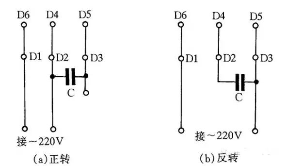
Figure 4 JX07A-4 type single-phase capacitor running motor wiring method
Figure 4 shows the wiring method of the JX07A-4 single-phase capacitor running motor. The motor power is 60W, and the 220V/50Hz AC power supply has a current of 0.5A. Its speed is 1400 rpm. The capacitor is made of a product with a withstand voltage of 400~500V and a capacity of 8μF. Figure 4(a) shows the forward wiring and Figure 4(b) shows the reverse wiring.
Five, single-phase hair dryer wiring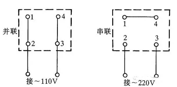
Figure 5 Single-phase hair dryer four outlet terminal wiring method
Some single-phase hair dryers lead to 4 terminals, and the wiring method is shown in Figure 5. The method of connecting and connecting should be connected to 110V AC power supply, and the serial connection should be connected to 220V AC power.
Six, Y100LY series motor wiringCurrently, Y series motors are widely used. Y series motors have the advantages of small size, beautiful appearance and power saving. There are two ways of wiring: one is â–³ shape, its terminal W2 is connected with U1, U2 is connected with V1, V2 is connected with W1, and then connected to the power supply; the other is Y-shaped, terminal W2, U2 V2 is connected, and the remaining three terminals U1, V1, and W1 are connected to the power supply. Wiring is shown in Figure 6.
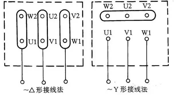
Figure 6 Y100LY series motor wiring method
Seven, low voltage transformer short circuit protection circuitAt present, the working light and running light of the machine tool use a low-voltage transformer to provide a safe voltage of 36V. Since the luminaire often moves during use, it is prone to short-circuit faults, causing the fuse to blow or even burn out the transformer. If you use a 36V small intermediate relay or a 36V AC contactor as the on/off switch of the transformer, you can avoid burning the transformer. The line is shown in Figure 7.

Figure 7 Low-voltage transformer short-circuit protection circuit
Working principle: After closing S, press button SB1, the transformer can output 36V low voltage, so that the relay or AC contactor KA pulls in. After the button SB1 is released, the KA self-locking contact keeps the KA in close contact and continues to energize the transformer. If the transformer secondary has a short-circuit fault, the relay coil voltage is zero. At this time, the KA is de-energized and the transformer power is disconnected to protect the transformer from damage.
Eight, speed motor 2Y/2Y wiring methodFigure 8 shows the method of connecting the lead wires of the 2Y/2Y motor two-speed stator wire set. The connection according to Fig. 8(a) is a kind of rotation speed, and connected according to Fig. 8(b) to obtain another rotation speed.
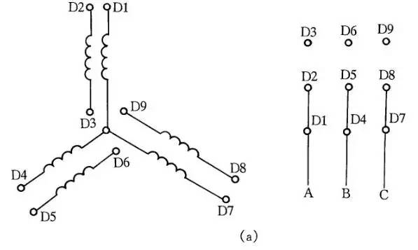
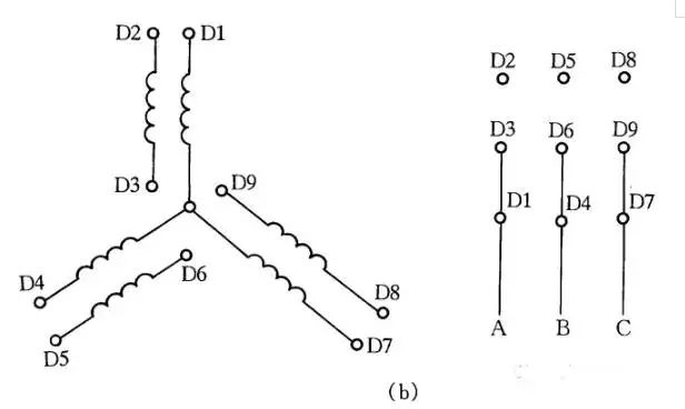
Figure 8 Two-speed motor 2Y/2Y wiring method
Nine, DC electromagnet fast demagnetization lineAfter the DC electromagnet is powered off, there may be adverse consequences due to the presence of residual magnetism. Therefore, we must try to eliminate residual magnetism. In Fig. 9, YA is a DC electromagnet coil, and KM is a contactor that controls YA to start and stop. When KM is pulled in, YA is energized and energized; when KM is reset, YA is disconnected from DC and fast demagnetization is performed.
The working principle of fast demagnetization is: after the DC electromagnet is de-energized, the AC power is charged to the capacitor C through the bridge rectifier and YA. As the voltage across the capacitor C increases, the charging current becomes smaller and smaller, and the current through the YA It is also alternating, so that the electromagnet is quickly demagnetized. The capacity of the capacitor C is determined according to the actual conditions of the electromagnet. R is a discharge resistor.
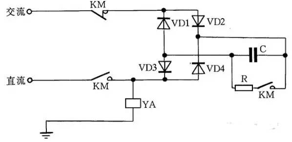
Figure 9 DC electromagnet fast demagnetization line
X. AC contactor emergency wiring lacking auxiliary contactsWhen the auxiliary contact of the AC contactor is damaged and cannot be repaired and is in urgent need of use, the wiring method shown in Figure 12 can be used to meet the emergency use requirements. Press SB1 and the AC contactor KM pulls in. After the button SB1 is released, the KM's contact doubles as a self-locking contact, making the contactor self-locking, so the KM remains engaged.
In the figure, SB2 is the stop button, and when it stops, the time for pressing SB2 is longer. Otherwise, after the button is released by hand, the contactor is closed again to keep the motor running. This is because the power supply voltage is cut off, but due to the inertia, the rotor of the motor still rotates, and the stator winding generates an induced electromotive force. Once the stop button is quickly reset, the induced electromotive force is directly applied to the contactor coil, causing it to re-engage. The motor continues to run. When the contactor coil voltage is 380V, it can be wired as shown in Figure 12(a); when the contactor coil voltage is 220V, it can be wired as shown in Figure 12(b). The wiring of Figure 12(a) also has the drawback that when the motor is stopped, its lead wire and motor are energized, making maintenance less secure. Therefore, this type of line can only be used in emergency situations, and the main power switch QS of the control motor should be disconnected when servicing the motor. This should be especially noted.
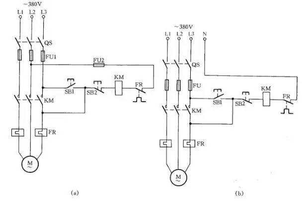
Figure 12 AC contactor emergency wiring without auxiliary contacts
Eleven, single-phase capacitor motor circuitThe single-phase capacitor motor has large starting torque, small starting current and high power factor, and is widely used in household appliances, such as electric fans and washing machines. In order to facilitate maintenance and installation, the wiring method commonly used for such motors is now introduced.
Figure 16 (a) is a reversible control circuit that operates the switch S2 to change the steering of the motor, which is typically used in domestic washing machines.
Figure 16 (b) is the wiring line with auxiliary winding, toggle switch S, can change the tap of the auxiliary winding, that is, change the actual withstand voltage of the main winding, thus changing the speed of the motor, this wiring method is often used on electric fans.
Figure 16 (c) shows the wiring line of the capacitor motor with reactor speed regulation. The speed can be changed by the in-line insertion of the reactor windings, which acts as a step-down in the line, by adjusting the amount of winding in the reactor windings. This method is currently widely used in household electric fan lines. When starting the motor, it is usually dialed to the "1" block, which is the high gear. At this time, the reactor is not connected to the line, so that the motor starts at full pressure, and then dial "2" or any gear to adjust the motor speed. .
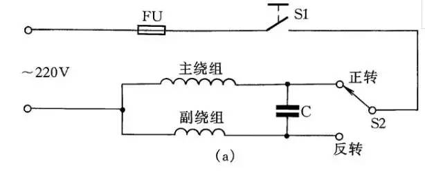
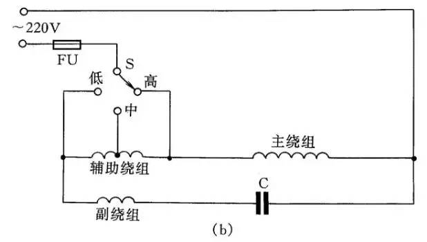
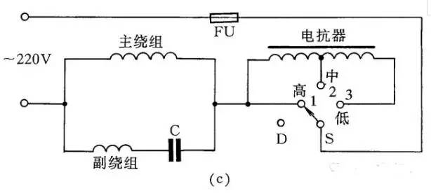
Figure 16 Single-phase capacitor motor circuit
Twelve, three-phase asynchronous motor changed to single-phase running circuitIf only a single-phase power supply and a three-phase asynchronous motor are available, the parallel capacitor can be used to change the three-phase asynchronous motor to single-phase operation.
As shown in Fig. 19, Fig. (a) is a Y-connected motor connection method, and Fig. (b) is a delta connection motor connection method. In order to increase the starting torque, the starting capacitor CQ is connected to the line at startup and exits after the startup is completed.
Calculation formula of working capacitor CG capacity:
CG=1950I/Ucosφ(μF)
Where: I is the rated current of the motor; U is the single-phase supply voltage; cosφ is the power factor of the motor. When the working capacitance is calculated, the starting capacitor is selected from 1 to 4 times the working capacitor.
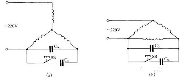
Figure 19 Three-phase asynchronous motor changed to single-phase operating line
The shockproof pressure sensor is the most commonly used sensor in industrial practice. It has shockproof function and has a certain benign response in case of various shaking. It is widely used in various industrial automatic control environments, including water conservancy and hydropower, railway transportation, intelligent construction, production automatic control, aerospace, military industry, petrochemical, oil well, electric power, ship, machine tool Pipeline and many other industries.
The integrated sensor is manufactured with standard process technology for producing silicon-based semiconductor integrated circuits. Usually, some circuits used for preliminary processing of the measured signal are also integrated on the same chip.
Shockproof Pressure Sensor,Vibration-Resistant Pressure Sensor,Shock Resistant Pressure Sensor,Waterproof Shockproof Pressure Sensor
Taizhou Jiabo Instrument Technology Co., Ltd. , https://www.taizhoujbcbyq.com