I went to a friend a few years ago and mentioned that the cost of the customer is very high now, especially in the toy industry, which is already one cent per cent to calculate the cost of the product. Friends feel that in order to save costs, the solution provider is racking his brains to think about various implementation methods, saying that in order to save costs, it is hard to use the single-chip IO to realize the function of two buttons, which makes him quite surprised, for a long time no I want to understand the principle. An IO implements two buttons, which sounds really novel. Since others can achieve it, I think I should be able to do it. It seems that I have to find a way to achieve it.
I have a habit. When I encounter certain problems, I will try to solve the problem before going to bed. If I think about it, I will fall asleep. If the answer to the question is not found, it is not necessarily. I know how to use a IO to implement multiple buttons. Most of these methods use the IO to support the ADC function. After the resistor is divided, the voltage is judged by the read voltage. If the IO does not support the ADC function, it is not impossible. The ADC can be implemented by capacitor charging and discharging, so that the measurement is indirectly performed by ordinary IO. (See my previous article on keyboard scanning.) The first feeling of using two IOs to implement two buttons is that I may need to use the principle of capacitor charging and discharging, so I found the way to achieve it.

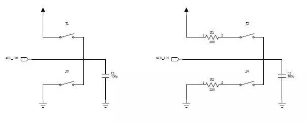
First look at the left part of the figure. If MCU_IO1 is a bidirectional IO port, suppose the MCU program is processed according to the following process. What results will be obtained?
1. MCU_IO1 is set to output, output high level for a period of time, at this time capacitor C1 will charge, and finally the voltage on C1 is close to the power supply voltage.
2. MCU_IO1 is set as input. If J1 and J2 are not pressed, MCU_IO1 can be understood as a resistor with a large resistance. The charge on capacitor C1 will be gradually released through this resistor, so the voltage on C1. Will gradually reduce to zero. Because the voltage drop on C1 requires a process, when MCU_IO1 is set as an input, read the status of MCU_IO1 immediately. What results will be read at this time? Obviously it is a high state 1.
3. Set MCU_IO1 as output and output low for a period of time. Obviously, regardless of the state of capacitor C1, as long as MCU_IO1 outputs low time for a long time, the voltage on C1 should be close to zero.
4. Set MCU_IO1 as input. If J1 and J2 are not pressed, MCU_IO1 reads low level 0. If J1 is pressed, let's take a look at these four steps. At this time, capacitor C1 has been forced to the power supply. MCU_IO1 has no effect on its charge and discharge. In step 2, the status read by MCU_IO1 is still 1, but in The state read by MCU_IO1 in step 4 is no longer 0, but becomes 1. If J2 is pressed, the same four steps are also observed. At this time, capacitor C1 is forcibly connected to the ground, and MCU_IO1 also loses its charge and discharge. In step 2, the state read by MCU_IO1 becomes 0, but in step 4, MCU_IO1 reads. The status reached remains at 1. Here I think everyone should have understood the implementation method. According to the MCU_IO1 status read in the four steps, it can be judged whether J1 and J2 are pressed.
Now that you have found a way, is it all right? Otherwise, we have to go back and see if this method is reliable enough. If J1 is pressed, capacitor C1 is directly connected to the power supply. When MCU_IO1 output is low, the low level of MCU_IO1 output is directly shorted to the power supply. If it is not good, it will burn out MCU_IO1. Similarly, when M2 is pressed, MCU_IO1 output is high. same question. There is a more serious problem than this, if the user presses J1 and J2 at the same time, ha! Actually, the power supply and the ground are directly short-circuited. The consequence of this is that the power supply part of the whole product is a smoky thing, so don't think that the product can still work.
Don't worry, take a look at the right half of the previous circuit diagram. Connect a 220 ohm resistor to each of the switches J3 and J4. This circuit will not short-circuit regardless of how J3 and J4 are pressed. Press the previous four. In one step, it can be judged whether J3 and J4 are pressed, but if J3 and J4 are pressed at the same time, the recognition judgment cannot be made.
IEEE 1394/Firewire Connector Overview
The IEEE 1394 connector series is capable of accommodating data rates up to 400 megabytes per second for serial transmission-consists of six-position connectors (for connections of computers to peripherals), and four-position connectors (for connections of digital AV equipment. We offer a screw thread size of M1.6 and two types of headers: dual inline package (DIP) and surface-mount technology (SMT). These four-position connectors help us manage a wide range of device designs and are suitable for DVD, set-top box, etc. The cable assemblies are also available with four-position to four-position type, for connection of AV equipment; four-positions to six-positions of transition type, for connections of PC and AV equipment; and six-position to six-position type for connections of PC and peripherals.
IEEE 1394 Connectors Product Features
Conforms to IEEE 1394 standard
Easy connections for plug and play devices
Available for wide range of connectors
DIP and SMT types available for PCB side
For 0.8mm and 1.6mm PC boards, M1.6 and M2.1 (4-position) panel mounting screw thread sizes
Use for automatic mounting machines with embossed tapes (4-position)
Fire Wire (IEEE 1394) Connector Wire to Borad Connectors
No of Contacts 4, 6, 9
Type
4pin IEEE 1394 Connector Female PCB Mounting Straight
4pin IEEE 1394 Connector Female PCB Mounting Right Angle
6pin IEEE 1394 Connector Female PCB Mounting Straight
6pin IEEE 1394 Connector Female PCB Mounting Right Angle
4pin IEEE 1394 Connector Male Wire Moulding type
6pin IEEE 1394 Connector Male Wire Moulding type
9pin IEEE 1394 Connector Male Wire Moulding type
9pin IEEE 1394 Connector Female PCB Mounting Right Angle
IEEE 1394 Connector With Female SMT 04P
IEEE 1394 Connector With Female SMT 09P

IEEE 1394 Connector Application:
IEEE1394 (Firewire) interface, IEEE1394 is a serial standard. .Like USB, IEEE1394 also support hotplug peripherals and can provide power for peripherals,
eliminating the need for built-in power supply. IEEE1394 supports multiple devices as well as synchronous data transmission.
Cameras
Camcorders
Scanners
Printers
DVD Players
Set-Top Boxes
Computer Monitors
Audio Video Receivers
Hard Drives
Audio Recording Devices
1394 Connector,Ieee 1394 Connectors,1394 Usb Connector,1394 Pcb Connector,Firewire Connector,IEEE 1394 USB Connector,1394 Firewire Connector
ShenZhen Antenk Electronics Co,Ltd , https://www.antenkwire.com