The waveguide slot array antenna has easy-to-control aperture amplitude, high radiation efficiency, strong directivity and compact structure, and easy to realize low side lobes or even low side lobes, so it has wide applications in radar and communication fields. The high frequency simulation software HFSS has a wide range of applications in the field of electromagnetic simulation, with high simulation accuracy and high stability. Using the 3D modeling capabilities of HFSS, simple model creation problems can be easily solved, but there is no particularly effective way to build complex antenna structure models, making the modeling process cumbersome, time consuming, and error prone. Using the VBScript script function provided by HFSS, the software can be re-developed with VBScript as the interface. Using Matlab to call HFSS collaborative modeling and simulation can simplify the operation of model establishment and save design time.
In this paper, a fast modeling method for a waveguide slot antenna is proposed, and a waveguide wide-edge crack array antenna is designed. Taking the waveguide slot antenna as an example, Matlab is used to establish model simulation with HFSS, and the simulation results are analyzed.
2. Basic theoryA waveguide slot antenna is an antenna that is slit on a wide wall or a narrow wall of a waveguide, and electromagnetic waves transmitted in the waveguide can radiate to the outside through the slot.
There are usually several types of slits, such as wide-edge offset slits, wide-edge inclined seams, and narrow-edge inclined slits. According to the form of the waveguide terminal, the waveguide slot array antenna can be divided into a row wave array and a standing wave array. The waveguide terminal of the traveling wave array is connected to the absorption load. The cell spacing is slightly larger or slightly smaller than λg /2. The standing wave array is connected to the short-circuiting slider at the terminal λg /4, and the cell spacing is λg /2. This paper designs a waveguide. Standing wave array antenna.
2.1 Theoretical analysis of waveguide slot antenna
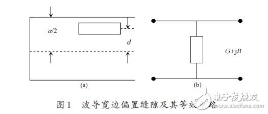
The radiation gap on the waveguide radiates energy to the outside, causing the change of the waveguide load. It is convenient to apply the transmission line theory to analyze the working state of the waveguide, and the corresponding gap is equivalent to the impedance connected in series with the transmission line or the parallel admittance, and then establish corresponding correspondence. The circuit model can be used to determine the equivalent impedance or admittance of each slot. The Stevenson equivalent circuit method is to calculate the calculation formula of the rectangular waveguide gap based on the transmission line theory and the Green's function of the waveguide mode. Figure 1 shows the waveguide wide-side longitudinal offset gap and its equivalent circuit.
The normalized equivalent resonant conductance is:

Comparing the software simulation with the calculation result of the formula (1) is 10-2 orders of magnitude, which shows that the calculation accuracy of the application formula (1) can meet the design requirements.
2.2 waveguide slit standing wave array design
The N-cell waveguide wide-side offset slot array antenna is designed by weighting the slot excitation amplitude and the sidelobe level Ro according to the Taylor distribution. The parameter A is determined by the sidelobe level Ro:
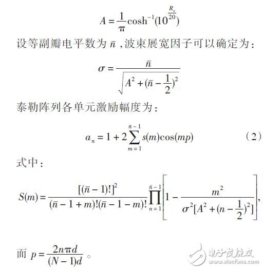
Therefore, from equation (2), the excitation amplitude value an of each slot conforming to the Taylor distribution can be calculated and substituted into equation (3):

The normalized conductance g of each slit is obtained, and the obtained normalized conductance value is substituted into the equation (1), so that the offset of each slit can be obtained.
2.3 Matlab collaborative HFSS modeling and simulation
Design a waveguide slot array antenna with a center frequency of 10 GHz, SLL = -25 dB, n ˉ = 4, and N = 21. The excitation amplitude an and the gap offset d of each slit are synthesized by the equations (1) to (3). The resonant length of the slot can be simulated by HFSS. The simulation model is shown in Figure 2. The slit width l is the scan variable. The l value when im(Y) = 0 is the slot resonance length.
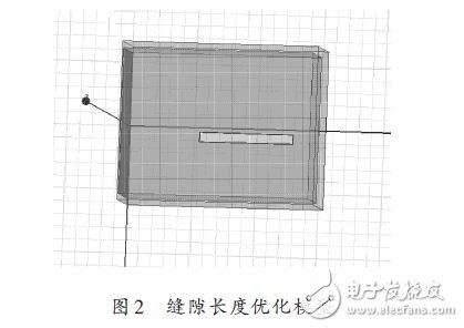
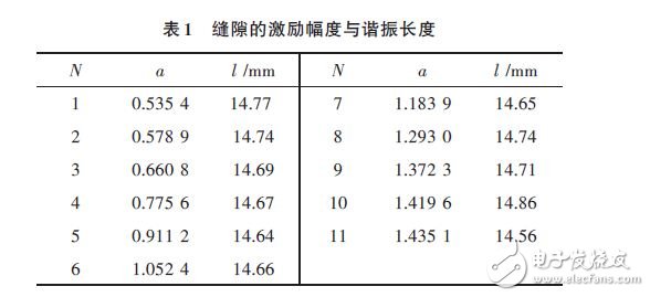
Table 1 is the excitation amplitude and resonance length parameters of a set of Taylor distribution gaps. The gaps 12~21 are symmetric with the slots 1~10. HFSS provides the VBScript scripting language function. Matlab can call HFSS to establish the corresponding model through this interface, and realize Matlab collaborative HFSS modeling and simulation.
In Matlab, you need to set the following: set HFSS and generated VBScript path; write waveguide model, excitation and boundary condition program; run m file to generate VBScript, call HFSS to build model as shown in Figure 3.
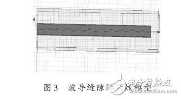
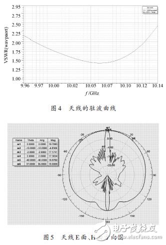
The waveguide size is 22.86 mm & TImes; 10.16 mm, the waveguide wall thickness is 1 mm, the feed port is λg /2 from the center of the slot, the center of the end slot is λg /4 from the terminal, and the terminal is short-circuited. It can be seen from the standing wave curve of Fig. 4 that the bandwidth of the standing wave is less than 2 is about 150 MHz. It can be seen from Fig. 5 that the lobe width of the E plane is about 5°, the width of the H plane is 76°, and the antenna gain is 19.7 dB, first sidelobe -24.5 dB, meeting design requirements.
In this paper, a wide-edge cracked antenna with a sidelobe level of -25 dB and a gap number of 21 is designed with Taylor's amplitude weighting. Using the VBScript function of HFSS as the interface, the corresponding program is written in Matlab, the VBScript script is generated, and then the model of the waveguide slot antenna is established by calling HFSS, and the simulation analysis is carried out. It can be seen from the simulation results that the antenna meets the design requirements, and also demonstrates the feasibility of using Matlab to cooperate with the HFSS modeling method. When building a more complex antenna model, for example, the number of slots of the waveguide is several tens or even hundreds, because the gap parameters are not the same, it cannot be completed in batches by using a simple copy operation in HFSS. Matlab modeling, the advantages are very obvious.
Our company specializes in the production and sales of all kinds of terminals, copper terminals, nose wire ears, cold pressed terminals, copper joints, but also according to customer requirements for customization and production, our raw materials are produced and sold by ourselves, we have their own raw materials processing plant, high purity T2 copper, quality and quantity, come to me to order it!
Copper Connecting Terminals,Cable Lugs Insulated Cord End Terminals,Pvc Insulated Cord End Terminal,Cable Connector Insulated Cord End Terminal
Taixing Longyi Terminals Co.,Ltd. , https://www.longyicopperlugs.com