The main electric appliance is used to close and open the control circuit to control the starting, stopping, braking and speed regulation of the electric motor in the electric drive system. The main electric appliance can directly act on the control circuit, or it can act indirectly on the control circuit through the electromagnetic electric appliance.
In the control system, the main electric appliance is an electric appliance that specifically issues commands, directly or indirectly through the electromagnetic electric appliance to the control circuit. It is often used to control the starting, stopping, speed regulation and braking of electric motors in electric drive systems.
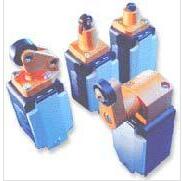
This article mainly introduces the function of the push button switch, position switch, energy switch and detailed structure diagram.
First, the button switch
A push button switch is a type of control switch that is operated by human power (usually a finger or palm) and has a stored energy (spring) reset. The contact of the button allows the passing current to be small, generally not exceeding 5A. Therefore, in general, it does not directly control the main circuit, but sends commands or signals to control the contactors, relays, etc. in the control circuit, and then go to them. Control the on/off, function conversion or electrical interlock of the main circuit.
1, structure
The push button switch is generally composed of a button cap, a return spring, a bridge movable contact, a moving and closing static contact, a strut link and a casing, as shown in the figure.
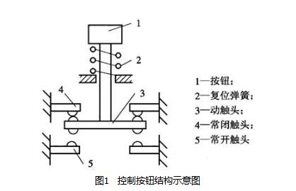
During operation, push the button cap down, the bridge type moving contact will move downwards, first break with the dynamic breaking contact, and then connect with the moving static contact. Once the operator's finger leaves the button cap, it is reset. Under the action of the spring, the moving contact moves upwards to restore the initial position. During the reset process, the moving contact is first broken, and then the moving contact is closed.
Second, the position switch
The position switch includes a travel switch (limit switch), a micro switch, a proximity switch, and the like.
(1) Travel switch
The travel switch is a switch that responds to the travel of the working machine and issues commands to control its direction of motion and stroke. It is mainly used for machine tool, automatic production line and other mechanical limit and program control.
1, structure and working principle
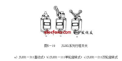
The basic structure of each series of travel switches is generally the same, consisting of a contact system, an operating mechanism and a housing. Common types are direct-acting and roller-type. The shape of the JLXKl series travel switch is shown in Figure 5-19.
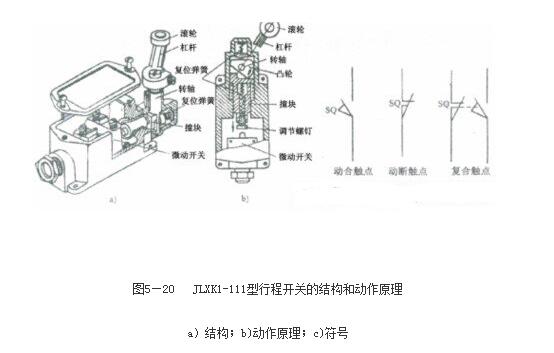
The operation principle of JLXKl series travel switch is shown in Figure 5-20. When the armature of the moving part presses the roller 1 of the stroke switch, the lever 2 rotates together with the rotating shaft 3, so that the cam 7 pushes the collision block 5, and when the collision block is pressed to a certain position, the micro switch 6 is pushed to move quickly, so that Its breaking contact is open and the moving contact is closed.
There are two types of contact action of the stroke switch: creep type and momentary type. The peristaltic contact structure is similar to the button, which is characterized by simple structure and low price, and the speed at which the contact is separated depends on the moving speed of the mechanical arm. When the moving speed of the iron is less than 0.47m/min, the contact is too slow, and the arc burning contact is easily generated, thereby reducing the service life of the contact, and also affecting the reliability of the action and the positional accuracy of the stroke control. In order to overcome these shortcomings, the travel switch generally employs a momentary type contact having a quick change action mechanism. The contact speed of the momentary type of the stroke switch is independent of the moving speed of the arm, and the performance is obviously superior to the creep type.
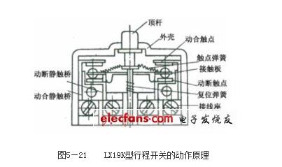
The LXl9K type travel switch is a momentary type, and its working principle is shown in Figure 5-21. When the arm of the moving part hits the jack 1, the jack moves downward, and the spring 4 is compressed to store a certain amount of energy. When the ram moves to a certain position, the spring force direction of the spring changes, and the stored energy is released, completing the jump quick change action. When the retaining iron leaves the ejector rod, the ejector rod moves up under the action of the spring 7, moves up to a certain position, and the contact bridge 5 instantaneously performs quick changeover, and the contact quickly returns to the original state.
After the stroke switch is actuated, the reset mode has two types: automatic reset and non-automatic reset. The direct-acting and single-turn rotary modes shown in Figure 5-19a and b are automatic reset type. However, some of the stroke switches cannot be automatically reset after the action, as shown in Figure 5-19c. The contact can only be reset when the moving machine moves in the opposite direction and the arm stops the other roller from the opposite direction.
2, the role
In an electrical control system, the position switch functions to achieve sequential control, position control, and position status detection.
Third, universal switch
The universal transfer switch is actually a multi-gear, multi-loop combination switch, which is mainly used for the conversion of control lines and the conversion of electrical measuring instruments. It can also be used to control the starting, reversing and speed regulation of small-capacity asynchronous motors. Because the number of contact stops is large, there are many switching lines, and it is possible to control multiple circuits and adapt to the requirements of complex lines, it is called a universal transfer switch.
(1) Structure and working principle
The universal transfer switch is mainly composed of a contact system, an operating mechanism, a rotating shaft, a handle, a positioning mechanism and the like, and is assembled into a whole by bolts. Its shape and working principle are shown in Figure 5-23.
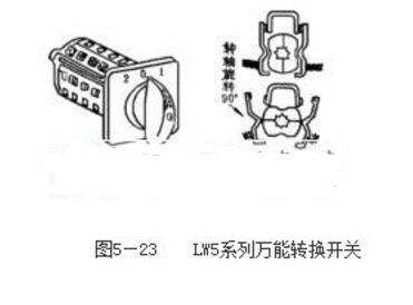
The contact system of the universal transfer switch is composed of a plurality of contact elements, each of which has a bakelite contact seat with a pair or three pairs of contacts in the middle, which are respectively operated by the cam through the bracket. During operation, the handle rotates the shaft and the cam together, and the cam can push the contact to open or close, as shown in Figure 5-26b. Due to the different shapes of the cams, when the handles are in different operating positions, the separation of the contacts is different, thereby achieving the purpose of switching circuits.
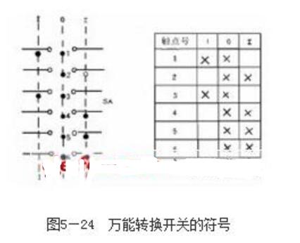
The symbol of the universal transfer switch in the circuit diagram is shown in Figure 5-24a. In the figure, "-" represents a contact, and a vertical dashed line indicates the position of the handle. When the handle is placed in a position, a black dot "·" is indicated on the dotted line below the contact in the on state. The on and off of the contacts can also be represented by the contact separation table as shown in Figure 5-26b. The "x" sign in the table indicates that the contact is closed, and the blank indicates that the contact is broken.
LED power supply, CCTV center power supply device, LCD display power supply.
We can meet your specific requirement of the products, like label design. The plug type is US/UK/AU/EU. The material of this product is PC+ABS. All condition of our product is 100% brand new. OEM and ODM are available in our company, and you deserve the best service. You can send more details of this product, so that we can offer best service to you!
Power Supply,5V Power Supply,12V Power Supply, 24V Power Supply
Shenzhen Waweis Technology Co., Ltd. , https://www.huaweishiadapter.com